Home » Others » Features of Mixed Flow Pump
Features of Mixed Flow Pump
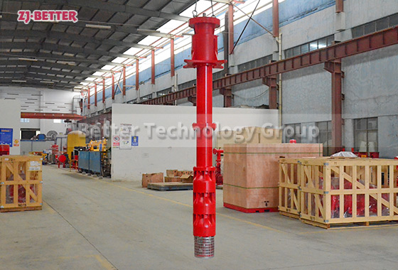
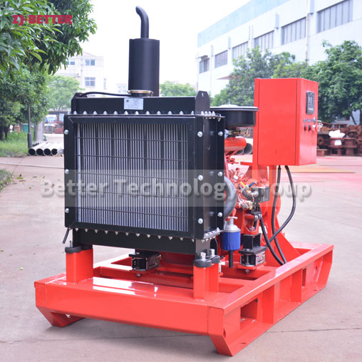
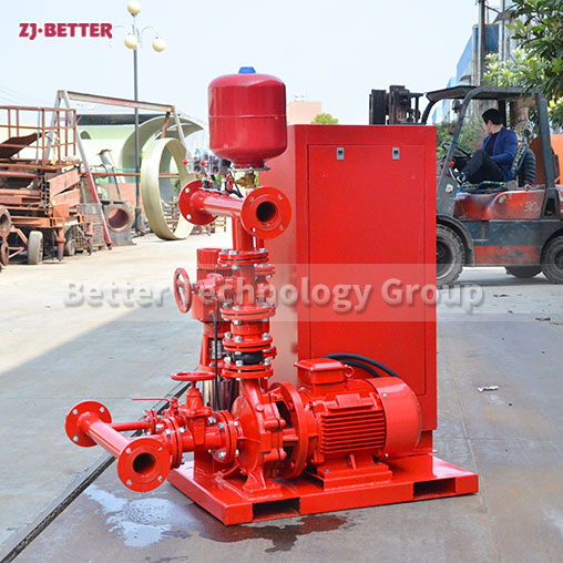
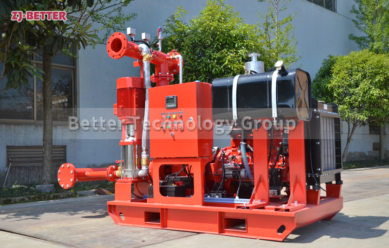
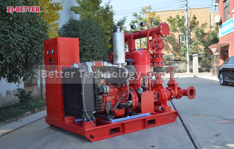
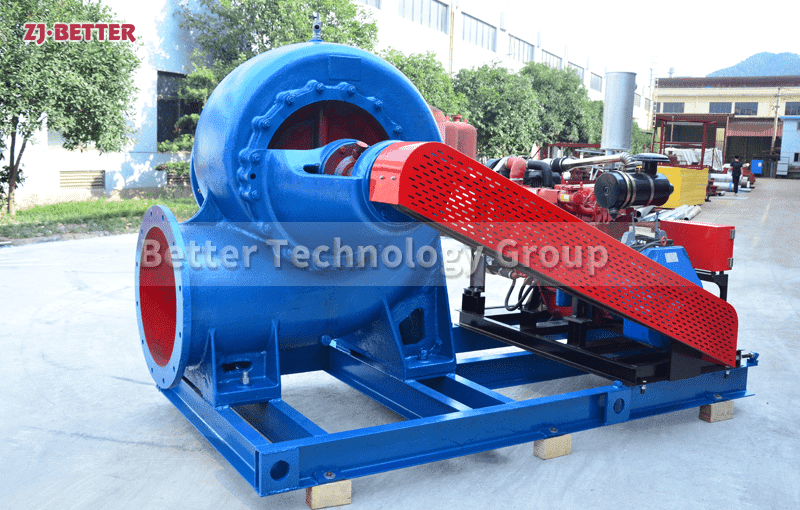
The pump’s performance range: flow 130~9000m³/h, head 3.5~22m. Simple structure, reliable use, easy installation, high efficiency, small body, light weight. Direct and variable actuations. The common movers are motor and diesel engine. Please note the model (power, rotating speed) of the mover so as to make sure of the norms of the clutch or the belt pulley. Viewing from the pump inlet, the impeller rotates counterclockwise generally (clockwise with 650HW-5, -7, -10 pump).
Contact US
Get Price
Share:
Content
Features:
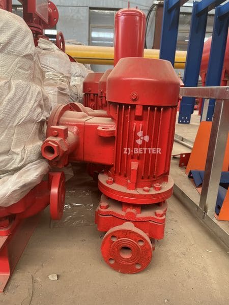
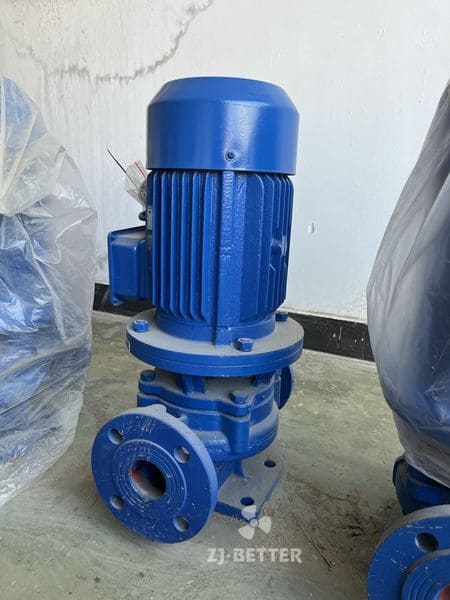
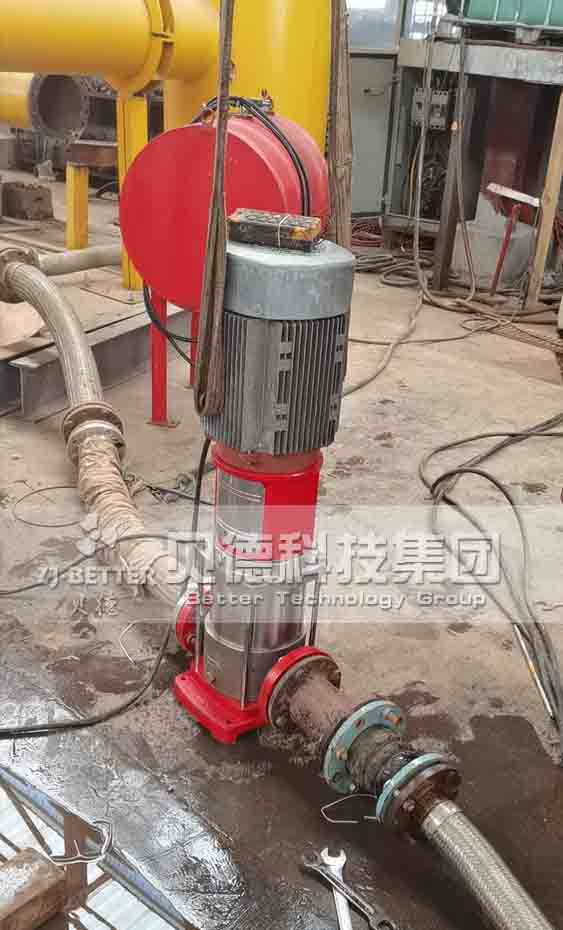
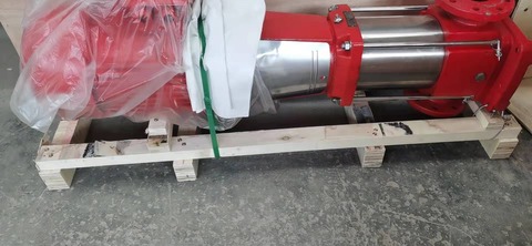
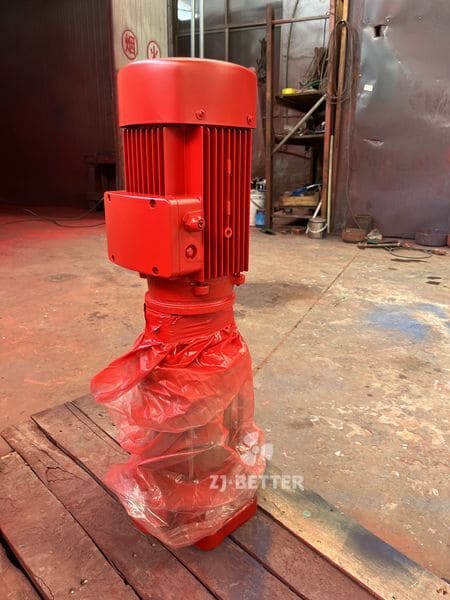
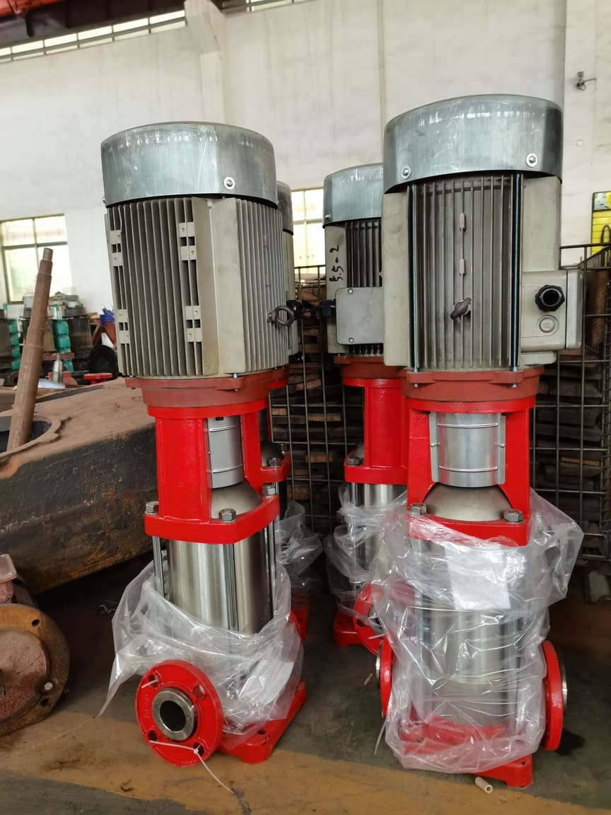
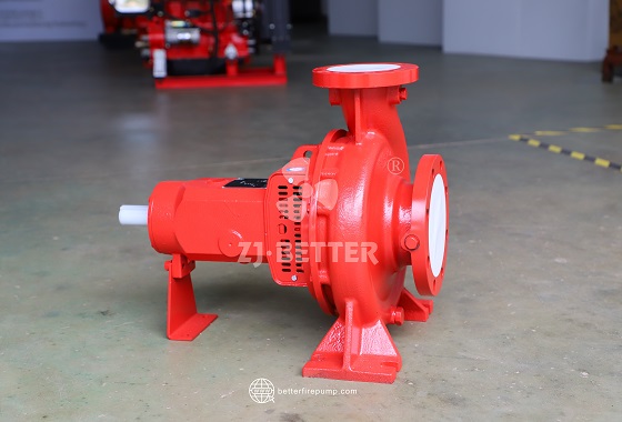
1. Pump Component: Model HW pump mainly consists of pump cover, impeller, pump casing, shaft, muff and bearing body (aperture ≤350mm) or bearing stand (aperture ≥400mm) etc. parts (Fig.1 and 2).
2. Standard Design: The pump cover is connected to the pump casing and the water-in pipe separately. There should a proper interval between the planes of both pump cover and impeller, too small interval will produce friction; while too big will cause the pressured water inside of the pump to flow back greatly to have the pump efficiency lowered. The practically used proper interval is 0.3~0.7mm (push the pump shaft to the pump inlet) and the interval can be adjusted through increasing or decreasing the paper pad thickness.
3. Spare Parts Standard: The shaft seal is formed with packing, packing gland, packing ring and the packing box on the pump casing (no packing ring with 150HW and 200HW pumps) and functions to prevent air from being sucked into the pump and too much water from flowing out axially.
4. Highly Integrated: The muff is used to protect the pump shaft and can be replaced after getting worn out.
5. Bearing Refueling: The pump shaft is supported with a single-line centripetal ball bearing. The bearing can be lubricated with lubricating oil-with he oil amount controlled in between the marking lines of the oil leveler rod; also with lubricating grease-filled during pump assembly or during use by means of removing both front and rear covers.
6. Convenient of Water Diversion: The screw hole on the top of the pump casing is used to prime leading water or link a vacuum pump for exhaust leading water.
7. Convenient to Usage: To widen the pump’s range of use and meet with the users’ different requirements, cut the outer diameter of the impeller or use an impeller of different performance (expressed with letter “A” etc. Added).
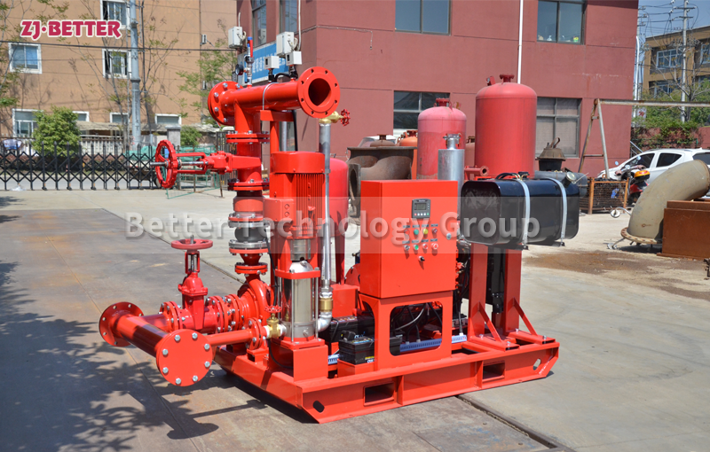
8. Optional Accessories: The accessories of 150~350HW pump include inlet and outlet dead and flexible elbows, foot valve, belt pulley or clutch; and of 400~650HW pump include inlet and outlet dead and flexible elbows, check valve, belt pulley or coupling.
2. Standard Design: The pump cover is connected to the pump casing and the water-in pipe separately. There should a proper interval between the planes of both pump cover and impeller, too small interval will produce friction; while too big will cause the pressured water inside of the pump to flow back greatly to have the pump efficiency lowered. The practically used proper interval is 0.3~0.7mm (push the pump shaft to the pump inlet) and the interval can be adjusted through increasing or decreasing the paper pad thickness.
3. Spare Parts Standard: The shaft seal is formed with packing, packing gland, packing ring and the packing box on the pump casing (no packing ring with 150HW and 200HW pumps) and functions to prevent air from being sucked into the pump and too much water from flowing out axially.
4. Highly Integrated: The muff is used to protect the pump shaft and can be replaced after getting worn out.
5. Bearing Refueling: The pump shaft is supported with a single-line centripetal ball bearing. The bearing can be lubricated with lubricating oil-with he oil amount controlled in between the marking lines of the oil leveler rod; also with lubricating grease-filled during pump assembly or during use by means of removing both front and rear covers.
6. Convenient of Water Diversion: The screw hole on the top of the pump casing is used to prime leading water or link a vacuum pump for exhaust leading water.
7. Convenient to Usage: To widen the pump’s range of use and meet with the users’ different requirements, cut the outer diameter of the impeller or use an impeller of different performance (expressed with letter “A” etc. Added).
8. Optional Accessories: The accessories of 150~350HW pump include inlet and outlet dead and flexible elbows, foot valve, belt pulley or clutch; and of 400~650HW pump include inlet and outlet dead and flexible elbows, check valve, belt pulley or coupling.
Inquiry
More Others